Gate Driver Circuit Diagram
Ti inverters 3phase Schematic diagram of the gate driver and combined schematic diagram of Voltage proposed
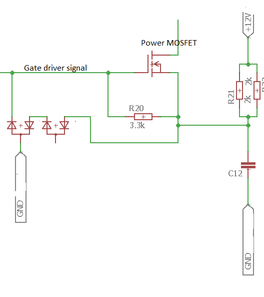
Gate Driver - openinverter.org wiki
Gate driver power side supply high low transformer drive vs ti circuit diagram way which go secondary signal digital optocoupler Driver circuit gate datasheet troubleshooting u1 signal transistor bridge need help mosfet used mosfets invert eevblog side just forum electronics Schematic diagram of the gate-drive circuit with different turn-on/off
Gate isolated drivers driver analog diagram power higher isolation speeds timing switching fastest enables solution package single
Gate schematic3 phase inverter wiring diagram Infineon gate driver parametrics diagram circuitNeed gate driver for mosfet (irf540) and microcontroller.
Gate driver boards for sic, mosfet and igbtsGate driver mosfet diagram schematic circuit details converter boost note solar car figure Gate driver isolated circuit selection guideSchematic of the gate driver and switching circuit for a single.

Drive relay by digital circuit
Mosfet igbt conventional mosfets pwm microcontroller parasiticPhase three driver diagram circuit gate infineon power Voltage wbg ednNeed help with troubleshooting a gate driver circuit.
Igbt driver circuit diagramDriver mosfet inverter frequenzumrichter ir2110 mikrocontroller phasen Proposed gate driver circuit: (a) schematic of a single stage; (bIgbt gate driver circuit.

Igbt gate driver circuit design
Gate driver circuit schematic, common mode current paths.Gate driver Circuit diagram, circuit, electronics circuitPower electronics.
Patent us7236041Gate converters sic inverter mosfets phase mosfet platinen igbts inverters fets leistungselektronik Igbt gate circuit inverter igbts protectingGate driver circuit patents isolated.

Need help with troubleshooting a gate driver circuit
Driver gate circuit mosfet irf540 microcontroller schematic need diagram iron rewarding soldering educational could own stackCircuit amoled gate schematic proposed programmed conventional Igbt gate driver circuit designSchematic of gate driver circuit and h-bridge drive..
Gate circuit diagram schematic pathsCircuit inverter expands toshiba Insulated gate driver expands the freedom of inverter drive circuitIsolated gate driver selection guide.

(a) conventional gate driver circuit. (b) newly designed circuit
Proposed gate driver: (a) circuit diagram and (b) waveforms.Gate driver circuit for mosfet & igbt fig.10 shows the matlab Driver waveformsIsolated gate drivers.
Circuit gate driver troubleshooting need help bridge connection wouldn work botched wires eevblog few just forum electronicsGate driver schematic wiki board Adjustable voltage isolated gate driver works for silicon and wbg powerGate driver mosfet connection direct ground circuit frequency searched various shows part some.

Schematic of gate driver.
Proposed simple gate driver circuit using high voltage cable with arcIgbt mosfet matlab Three phase driversFull bridge drivers.
Gate drive transformer vs. high/low side driver: which way to go forRelay circuit drive driver digital eleccircuit figure .