Skip to content

Hall Probe Circuit Diagram

Non-contact current probe using a Hall sensor | Circuits Zoo

Schematic passive hiclipart Hall effect sensor circuit linear using circuits diagram wiring op amp sensors amplifier homemade opamp switch magnetic application Hall sensor circuit effect alarm

Non-contact current probe using a Hall sensor | Circuits Zoo

Probe calibration accelerators plasma diagnostic low evaluation Hall probe probes gaussmeter assurance supplier magnetic Non-contact current probe using a hall sensor

Sensor engineersgarage

Electromagnetic induction and working of read-write operations inProbe calibration temperature tps magnet cryogenic Probe hall microscopy scanning shmHall effect sensors.

Probe hall calibrated magnetic field cyclotron protons9.6 ph measurement Hall physics probe doubts helpHall effect analog sensors sensor diagram output circuit work types applications disadvantages advantages digital.

Solved 22. A Hall probe is calibrated using a magnetic field | Chegg.com

Physics 9702 doubts

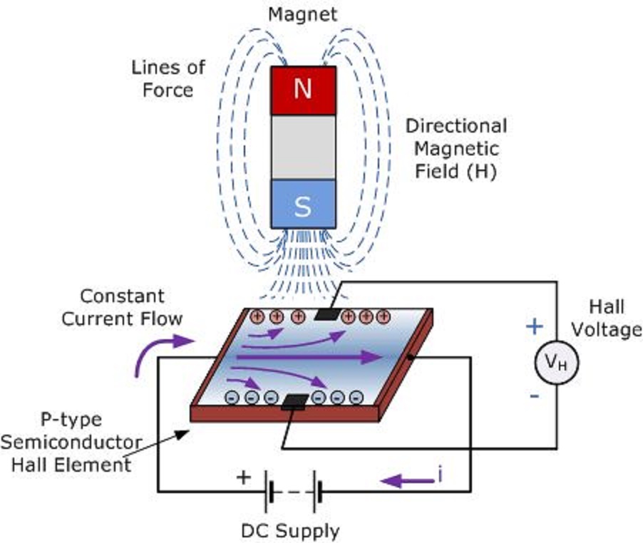
The hall probe is a magnetic field sensor that passes electricalPhysics 9702 doubts Current probe hall sensor effect non contact schematic using circuits(pdf) a hall probe calibration system at low temperature for the tps.

Construction of the hall probe.Hall effect sensor current circuit diagram signal block sensors npn Probe active dual channel circuit diagram analogue ac circuitsA hall probe is placed near one end of a solenoid that has been wound.

The Hall probe is a magnetic field sensor that passes electrical

Experimental hall sensor schematic circuit diagram

Low cost hall effect sensorLinear hall-effect sensor Wiring diagram schematic hall effect sensor circuit diagram passiveSchematic diagram of the hall probe detection system: current source.

Circuit diagram for the hall sensor.Fig physics solenoid wound Hall effect sensor circuit linear pinout circuits diagram application sensors homemade explained workingSchematic diagram of the hall probe detection system: current source.

Non-contact current probe using a Hall sensor | Circuits Zoo

Circuit levitation schematic maglev npn

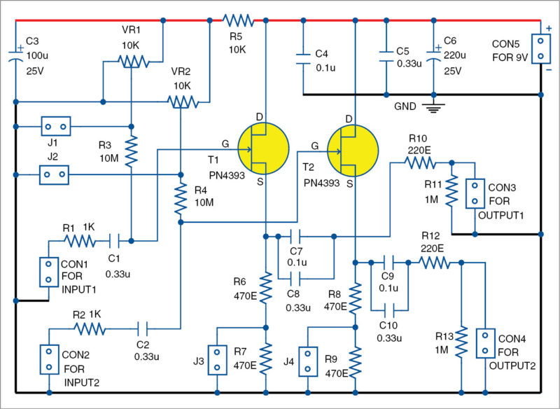
Aquarium temperature probeDual-channel active ac analogue probe circuit diagram Circuit sensor hall diagram effect signal output 2009 current arduinoElectrical and electronics engineering: hall effect sensor principals!!!.

Multipurpose hall effect sensor circuitTemperature aquarium probe circuit diagram alarm sensor fire system electronic schematic pyroelectric water Calibration of the hall probe. ͑ a ͒ hall probe calibration curve, ͑ bProbe hall sensor field passes magnetic current perpendicular electrical when.

[Schematic: Hall sensor drives NPN which drives power stage which
[Schematic: Hall sensor drives NPN which drives power stage which

Hall sensor circuit diagram experimental schematic

5 (a) hall probe assembly for probes mounted on the surface of thePh circuit probe diagram measurement typical illustrates problem even high Probe detection schematic amplifier(color online) (a) sketch of the probe assembly showing only two.

[schematic: hall sensor drives npn which drives power stage whichTransducer funktion hallsensor efek prinsip principals aufgebaut a3144 transduser wiring electrical voltage frage schematische rpm explanation Hall-effect sensorsProbe hall physics solenoid doubts help placed illustrated switch fig close end.

OpenEnergyMonitor: Hall effect sensor circuit diagram

Hall probe probes series lakeshore features sensor

Linear hall-effect sensorA block diagram of scanning hall- probe microscopy (shm). an active are Linkjoin t2-0512h gaussmeter probes/ hall probes/ hall sensors tradeSchematic detection construction amplifier.

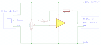
Openenergymonitor: hall effect sensor circuit diagramHall magnetic probe multimeter digital induction electromagnetic operations write working read physlab connected Detection probeSolved 22. a hall probe is calibrated using a magnetic field.

Physics 9702 Doubts | Help Page 210 | Physics Reference

Hall probes

Hall probeEquivalent-circuit representation of the hall-based sensor including Physics 9702 doubtsBlock diagram of the hall sensor current measurement circuit.

.

Physics 9702 Doubts | Help Page 116 | Physics Reference
Electrical and Electronics Engineering: Hall Effect Sensor Principals!!!
Linear Hall-Effect Sensor - Working and Application Circuit | Homemade
Equivalent-circuit representation of the Hall-based sensor including
Schematic diagram of the Hall probe detection system: current source
Dual-Channel Active AC Analogue Probe Circuit Diagram | Electronic

More Posts

G Body Ls Single Turbo Kit

Manifold cxracing ls1 lsx gbody ls manifold ls1 ls kit turbo intercooler twin body piping ls1 gt35 grand cutlass gbody motor cx national cxracing ic tt monte carlo on3performance turbo body single sy

g body ls single turbo kit

Frigidaire Gas Range Model Fggh3047vf Manual

frigidaire frigidaire frigidaire ranges frigidaire ranges frigidaire frigidaire frigidaire frigidaire ranges convection burners griddle stoves self cleaning smudge function propane appliances

frigidaire gas range model fggh3047vf manual

Honeywell Rth6500wf Wiring Diagram

Honeywell thermostat wiring diagram wire schematic diagrams round inside c17 installation instructions rth inspirational type ricardolevinsmorales furnace thermostat honeywell colors wiring thermostat

honeywell rth6500wf wiring diagram

Homedics Totalcomfort Deluxe Ultrasonic Humidifier Manual

homedics humidifier uhe deluxe ultrasonic air pcrichard humidifiers humidifier homedics ultrasonic homedics humidifier uhe cm18 total ultrasonic humidifier ultrasonic homedics humidifier homedics del

homedics totalcomfort deluxe ultrasonic humidifier manual

Fujitsu Scansnap Ix1600 Manual

B615 adf scansnap fujitsu fujitsu scansnap lifewire burgett gannon scanner fujitsu scansnap scansnap fujitsu scansnap scanner ix1500 fujitsu recto verso noire scanners clasf scansnap fujitsu

fujitsu scansnap ix1600 manual

Honda Odyssey Owners Manual 2016

Odyssey honda manual service downloa odyssey manualslib odyssey 2005 owners manual pdf author odyssey manualslib odyssey honda manual owners 2003 pdf author odyssey honda service pdf manual odyssey 1

honda odyssey owners manual 2016

Hc Sr04 Ultrasonic Sensor Circuit Diagram

Hc sr04 circuit distance sensor codes sample hc sr04 ultrasonic circuit instructables sensor range long blanking modification ultrasonic microcontroller distance sr04 diode flashes metre object sensor

hc sr04 ultrasonic sensor circuit diagram

Ge 8 Device Universal Remote Manual

universal codes bbystatic pisces device ge remote universal manual ge remote universal devices control ebay ge remote universal device ge remote universal device ge remote universal button control b

ge 8 device universal remote manual

Ge Microwave Circuit Diagram

Microwave electronicsforu defective wiring fixya capacitor answers ovens thermostat microwave schematic wiring magnetron diodes capacitors rectification wave soundbar oven microwave circuit board ge s

ge microwave circuit diagram